Week 02 · lesson
Lesson 1: Motherboard as the Compatibility Map
Core path: 42 minutes
A motherboard is not just the big board everything plugs into.
For a technician, it is the compatibility map for the whole system.
Before you buy a processor, RAM kit, storage device, expansion card, or case, the board tells you what can actually work together.
Start with form factor
Common desktop motherboard form factors include:
- ATX — larger board, more expansion room;
- Micro-ATX — smaller, often fewer slots;
- Mini-ITX — compact, limited expansion.
The board must fit the case, but physical fit is only the first check.
A component can fit physically and still be incompatible electrically, logically, or at the firmware level.
Read the board like a technician
Identify these major areas:
- CPU socket;
- DIMM slots for RAM;
- PCIe expansion slots;
- M.2 storage slots;
- SATA ports;
- 24-pin motherboard power connector;
- CPU power connector;
- front-panel headers;
- USB headers;
- fan headers;
- firmware/CMOS battery area.
The exact layout changes between boards, but the functions stay recognizable.
Compatibility has layers
Use this sequence whenever you evaluate a part:
- Physical compatibility — does it fit the socket, slot, connector, and case?
- Electrical compatibility — does the interface provide the correct signaling and power?
- Firmware/platform compatibility — does the board firmware support the component?
- System compatibility — will the whole configuration work together within power, cooling, and performance limits?
That is why "it plugs in" is not enough.
BIOS/UEFI is part of the compatibility map
Firmware settings can change whether a system boots, exposes a device, or enables a security/virtualization feature.
At A+ technician depth, recognize settings such as:
- boot order/options;
- USB permissions;
- Secure Boot;
- virtualization support;
- TPM-related security features;
- fan control and temperature monitoring;
- boot password;
- BIOS/UEFI setup password.
A technician should document the baseline before changing firmware settings. Changing several firmware options at once destroys useful evidence.
TPM and HSM are not the same thing
A TPM is a platform security component commonly integrated into or associated with the local system and used by features such as measured/trusted boot and encryption key protection.
A hardware security module (HSM) is a dedicated device/service class designed to protect and perform operations with cryptographic keys, typically at organizational/service scale.
For this course, the distinction is recognition-level:
TPM is tied closely to one platform. HSM is a broader dedicated cryptographic key-protection device/service category.
Example: the wrong CPU
A processor may look similar to another model but use a different socket generation.
If the CPU socket and motherboard do not match, stop there. Do not force the component.
Technician rule:
If a part requires pressure beyond the normal installation mechanism, re-check orientation and compatibility before doing anything else.
Student action
Create a motherboard inspection record with these columns:
| Interface/setting | What connects or changes here? | Compatibility/security question |
|---|---|---|
| CPU socket | processor | Does the CPU use this socket and supported platform? |
| DIMM slot | desktop RAM | Is the DDR generation correct? |
| PCIe slot | GPU/NIC/etc. | Is the slot/type appropriate? |
| M.2 slot | SSD | Does the slot support the drive's form factor/protocol? |
| Secure Boot | firmware security setting | Is the intended OS/platform configuration compatible with it? |
| TPM | platform security | Does the required OS/security feature depend on TPM capability? |
Add at least four more interfaces or firmware settings.
Evidence checkpoint
You are ready to move on when you can explain why these are different statements:
- "The component fits."
- "The component is compatible."
- "The firmware exposes/configures it correctly."
- "The system is configured securely for the required job."
Those are different claims, and technicians need evidence for each one.
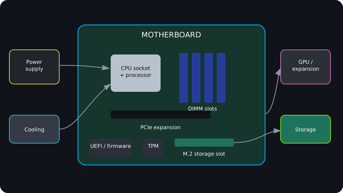
Diagrams open at a readable shape-aware scale. Zoom or expand when you need more detail.
Interactive hardware model
Inside the desktop: inspect, isolate, diagnose
Robotnix-original procedural model. No external 3D asset is loaded and nothing auto-rotates.Building the hardware model…
Guided inspection
Trace the service boundaries
Service symptom
Use the symptom to choose your first hardware boundary
Read the 3D model as text
- CPU + cooler: The processor executes instructions. Platform/socket compatibility, cooling, firmware support, and power delivery all matter.
- RAM: DIMMs provide volatile working memory. Capacity, generation, channel layout, speed support, ECC support, and seating can affect operation.
- GPU / expansion: The graphics card uses PCI Express expansion bandwidth and may require additional PSU power connectors and cooling space.
- M.2 storage: An M.2 module describes a physical form factor. The device and slot may use SATA or PCIe/NVMe, so interface support still has to be verified.
- Power supply: The PSU converts AC input into DC rails for the system. Treat it as a replaceable unit in class; never open it for internal service.
Motherboard inspection board
Locate the major board-level components and connect each physical location to a compatibility or no-POST service clue.
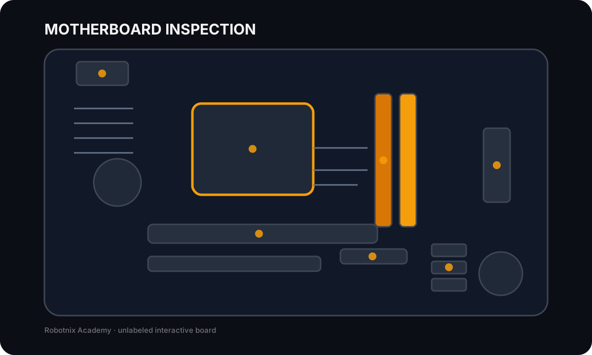
CPU socket
Job: Holds the processor and provides the electrical/mechanical interface to the motherboard.
Service clue: A physically similar processor is not enough. Socket, supported CPU family, firmware, power, and cooling must all agree.
Read the inspection board as text
- CPU socket: Holds the processor and provides the electrical/mechanical interface to the motherboard. Service clue: A physically similar processor is not enough. Socket, supported CPU family, firmware, power, and cooling must all agree.
- DIMM slots: Hold desktop memory modules and expose channel layout to the processor/platform. Service clue: No-POST after a memory change should push you toward seating, generation, supported capacity, ECC support, and channel placement.
- PCI Express slots: Provide high-speed expansion connectivity for graphics, networking, storage, and other add-in cards. Service clue: Check lane/slot compatibility, card seating, required supplemental power, firmware support, and whether the correct output path is being used.
- M.2 storage slot: Accepts supported M.2 modules, often carrying PCIe/NVMe or SATA signaling depending on the board. Service clue: M.2 describes a form factor, not automatically NVMe. Verify keying, length, interface support, and shared-lane limitations.
- SATA ports: Connect supported SATA storage devices to the motherboard controller. Service clue: A missing SATA drive can be a power, data-cable, port, firmware, controller-mode, or drive-health problem.
- 24-pin ATX power: Carries the motherboard's primary power feeds from the PSU. Service clue: A board can appear completely dead when the main connector is loose even if the PSU itself is functional.
- CPU 8-pin power: Supplies dedicated processor power near the CPU voltage-regulation area. Service clue: A system may power fans yet fail to POST if CPU power is missing or connected incorrectly.
Read it. Prove it.
Lesson knowledge checks
Answer from the lesson you just completed. Results stay in this browser and are not submitted.Why must a motherboard form factor match the case and power design?
Which motherboard feature provides expansion bandwidth for devices such as GPUs?
system flow
Follow a Workload Through Hardware
Input / Storage
A workload begins with incoming data or durable data read from storage.
RAM
Active instructions and working data are placed in fast volatile memory.
CPU
General-purpose instructions, control decisions, and coordination execute here.
GPU / I-O
Parallel graphics work or device transfers move through specialized processors and interfaces.
Output + Bottleneck Evidence
Observed delay, utilization, or throughput evidence identifies which resource is constraining the workload.
Read this concept flow as plain text
- Input / Storage. A workload begins with incoming data or durable data read from storage.
- RAM. Active instructions and working data are placed in fast volatile memory.
- CPU. General-purpose instructions, control decisions, and coordination execute here.
- GPU / I-O. Parallel graphics work or device transfers move through specialized processors and interfaces.
- Output + Bottleneck Evidence. Observed delay, utilization, or throughput evidence identifies which resource is constraining the workload.