Week 01 · lesson
Lesson 2: Open the Box
Today we stop treating the desktop as one object.
A technician sees a collection of replaceable systems with different jobs, connectors, risks, and failure symptoms.
The major internal components
When you remove the side panel from a typical desktop, identify these first:
- motherboard;
- CPU and cooler;
- RAM;
- storage devices;
- power supply;
- expansion cards;
- case fans;
- front-panel and internal cables.
Do not start unplugging things just because you can see them.
First map the machine.
Motherboard
The motherboard is the main circuit board that connects the system components.
Look for:
- CPU socket;
- DIMM slots;
- PCIe slots;
- SATA connectors;
- M.2 slots;
- 24-pin ATX power connector;
- CPU power connector;
- front-panel headers;
- fan headers;
- rear I/O ports.
The motherboard is also where compatibility becomes real. A CPU, RAM kit, storage device, or expansion card can be perfectly functional and still be wrong for a particular board.
CPU and cooling
The CPU executes instructions. The cooler removes heat from the processor package.
Do not separate those ideas.
A high-performance CPU with an inadequate cooler is not a high-performance system for long.
Inspect:
- CPU socket type;
- cooler mounting;
- fan connection;
- airflow direction;
- dust buildup;
- signs of thermal-paste problems or poor contact.
Do not remove the CPU or cooler unless the lab specifically directs you to.
RAM
Desktop memory normally installs into DIMM slots.
RAM is volatile working memory. It is not long-term storage.
Check:
- how many slots exist;
- which slots are populated;
- whether the modules are fully seated;
- notch alignment;
- retaining clips;
- module labels when visible.
Never force a DIMM into a slot. The notch is there for a reason.
Storage
Common desktop storage includes:
- 3.5-inch SATA HDDs;
- 2.5-inch SATA SSDs;
- M.2 SSDs, which may use SATA or NVMe depending on the device and slot.
The physical shape does not automatically tell you the protocol. That matters especially with M.2.
Power supply
The PSU converts incoming AC power into DC voltages used by the computer.
Identify the external PSU enclosure and its outgoing cables, but do not open the PSU.
Common connectors include:
- 24-pin motherboard power;
- 4+4 or 8-pin CPU power;
- PCIe or newer GPU power connectors;
- SATA power.
Lab: component census
Using a powered-off classroom desktop or the approved PC Anatomy visual, complete a component census.
For each component, record:
- component name;
- location;
- job;
- connector or slot;
- one likely failure symptom;
- whether it can be replaced independently.
Example:
| Component | Job | Connection | One possible symptom |
|---|---|---|---|
| RAM | active working memory | DIMM slot | boot failure, instability, memory errors |
Technician habit: photograph before disconnecting
Before removing a cable or component, capture the original state when policy allows.
A good service photo should show:
- connector location;
- cable orientation;
- neighboring components;
- enough context to reconstruct the original layout.
Documentation is part of repair work, not paperwork after repair work.
Evidence checkpoint
You are ready to move on when you can point to a system or model and correctly identify the motherboard, CPU cooling system, RAM, storage, PSU, expansion area, and major power/data connections.
Next we look at the connectors, ports, and interfaces that let these components communicate.
Visual reference
See the system before you troubleshoot it
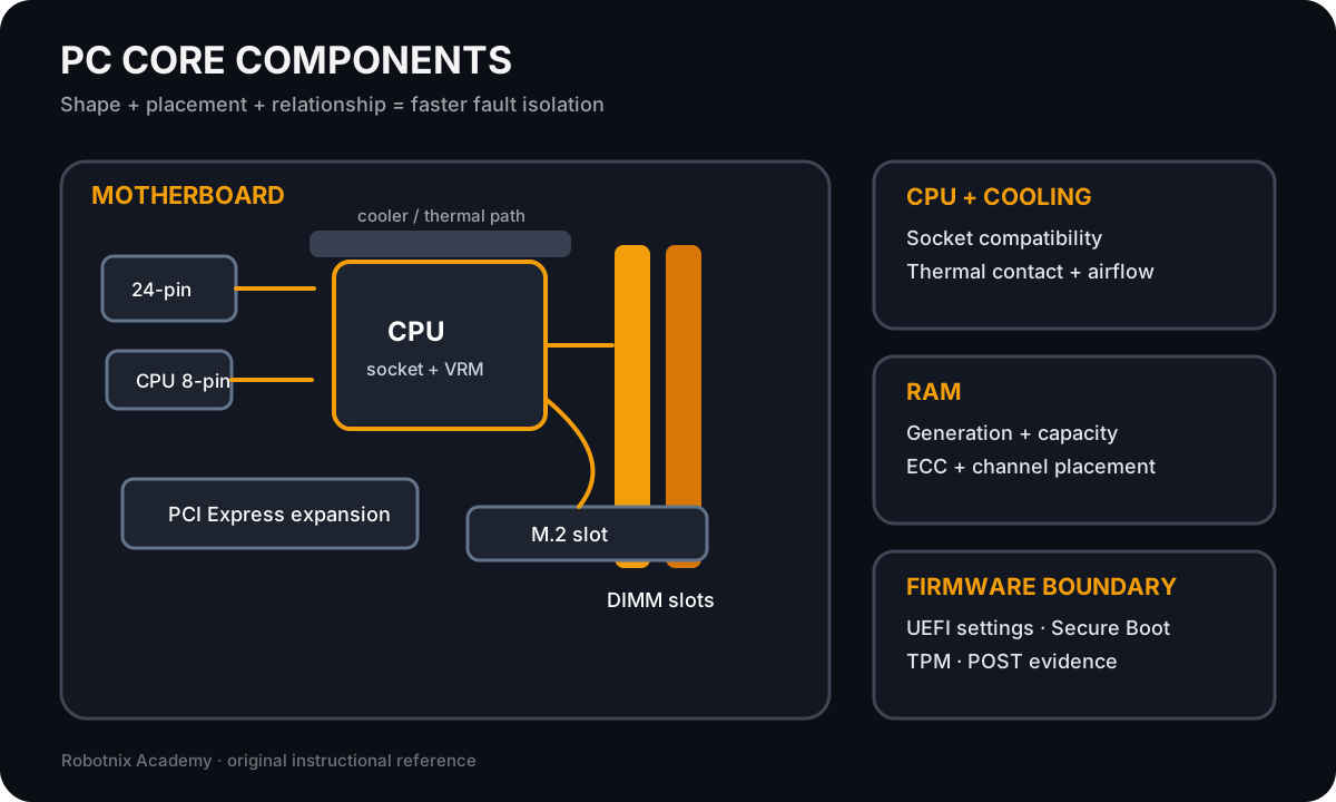
Use component shape, placement, and relationship clues to separate motherboard, CPU, memory, and cooling faults.
Use it for: Compare core PC components before compatibility and no-POST troubleshooting.
Read it. Prove it.