Week 04 · lesson
Lesson 1: Power Has a Path
Core path: 42 minutes
A PC can have the right CPU, RAM, storage, and graphics card and still do absolutely nothing.
Why?
Because every component depends on usable power reaching the correct connector.
This lesson is not about opening a power supply. Do not do that. A PSU can contain hazardous stored energy even after it is unplugged. We are learning the external power path and the connectors/specifications a technician can safely inspect.
What the PSU actually does
The power supply converts incoming AC power into regulated DC power used by the computer.
For technician reasoning, trace the path:
wall / UPS
→ AC input
→ PSU conversion
→ 3.3 V / 5 V / 12 V DC rails
→ motherboard / CPU / GPU / drives
→ component operation
If the path breaks early, everything downstream can look dead.
Input voltage matters
A+ expects recognition of common AC input ranges such as:
- 110–120 VAC;
- 220–240 VAC.
Many modern PSUs are auto-ranging, but some older/specialized units can use a manual selector. An incorrect input setting can damage equipment. Never change an input-voltage selector casually.
Output rails
PC power supplies provide regulated DC outputs including 3.3 V, 5 V, and 12 V rails used by different components/circuits.
You do not need to memorize every wire color. You do need to understand that "the PSU turns on" does not prove every required output path is healthy under load.
Know the common connectors
20+4 / 24-pin ATX
The main motherboard power connection. The 20+4 design can form the 24-pin connector used by modern ATX boards.
4+4 / 8-pin EPS CPU power
Provides CPU power near the processor socket. A board can have its 24-pin connector installed and still fail when required CPU power is missing.
PCIe / modern GPU power
Discrete graphics cards may require additional PSU power beyond what the PCIe slot supplies. Connector requirements vary by card and PSU.
SATA power
Used by SATA drives and some accessories.
Molex
A legacy peripheral-power connector that still appears in older systems and accessories.
PSU design choices
Modular PSU
A modular or semi-modular PSU allows some/all removable output cables. That can improve cable management, but modular PSU cables are not universally interchangeable between PSU models. Use only cables approved for that PSU.
Redundant PSU
Servers and higher-availability systems may use redundant power supplies so one PSU can fail while another continues supporting the system, depending on the design.
Redundancy is not the same thing as a UPS and does not eliminate every power failure domain.
Wattage rating
A 1000 W PSU does not force a computer to consume 1000 W. The rating describes available capacity under specified conditions.
A technician needs enough capacity for the actual system, reasonable headroom, correct connectors, and appropriate quality.
Energy efficiency
PSUs lose some energy as heat during conversion. Higher efficiency reduces conversion waste under rated conditions, but an efficiency rating does not prove the PSU has the correct wattage/connectors or that it is healthy.
Guided case: fans do nothing
Ticket:
Desktop worked yesterday. Today the power button produces no lights, no fans, and no display.
Do not start by replacing the motherboard.
Build a check order:
- Is the outlet or UPS providing power?
- Is the external power cable seated?
- Is the PSU switch/approved input configuration correct?
- With power removed, are required motherboard power connectors seated?
- Is the front-panel power-button connection plausible?
- What evidence would justify moving deeper into PSU or board diagnosis?
Student action: build a power map
For a desktop containing a motherboard, CPU, SATA SSD, and discrete GPU, create a power map that labels:
- AC input assumption;
- PSU;
- 3.3/5/12 V output concept;
- 20+4/24-pin motherboard power;
- CPU power;
- GPU power if required;
- SATA power;
- modular/redundant/efficiency characteristic if relevant;
- which component each path supports.
Then inject one missing connector or wrong PSU requirement and predict the symptom.
Evidence checkpoint
You are ready to move on when you can explain why:
- AC input and DC output are different sides of the PSU;
- 3.3 V, 5 V, and 12 V outputs exist for different system needs;
- 20+4 motherboard power and CPU power are different connectors;
- wattage alone does not prove compatibility;
- modular cables are not universally interchangeable; and
- a technician should never open a PSU as part of this classroom workflow.
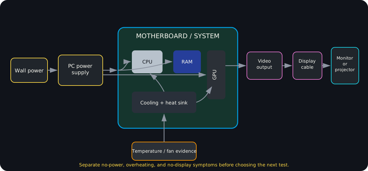
Diagrams open at a readable shape-aware scale. Zoom or expand when you need more detail.
Read it. Prove it.
Lesson knowledge checks
Answer from the lesson you just completed. Results stay in this browser and are not submitted.Which PSU output rail commonly supplies 12 V power for high-load system components?
Why should students never open a PC power supply in a classroom repair lab?
system flow
From Power-On to a Usable System
Firmware
Startup firmware initializes hardware and selects the next boot stage.
Boot Path
Boot code locates and transfers control toward the operating-system kernel.
Kernel
The kernel manages core hardware, memory, processes, filesystems, and device access.
Userspace Services
System services start above the kernel and provide background capabilities needed by applications.
Shell / Applications
Users interact through shells and applications after the lower startup layers are functioning.
Read this concept flow as plain text
- Firmware. Startup firmware initializes hardware and selects the next boot stage.
- Boot Path. Boot code locates and transfers control toward the operating-system kernel.
- Kernel. The kernel manages core hardware, memory, processes, filesystems, and device access.
- Userspace Services. System services start above the kernel and provide background capabilities needed by applications.
- Shell / Applications. Users interact through shells and applications after the lower startup layers are functioning.